
22 min read ·
Planning an Isolated Second-Battery System for a 2000 Silverado
An isolated auxiliary battery is possible on a gasoline-powered 2000 Silverado, but the evidence does not support a universal bolt-in procedure.
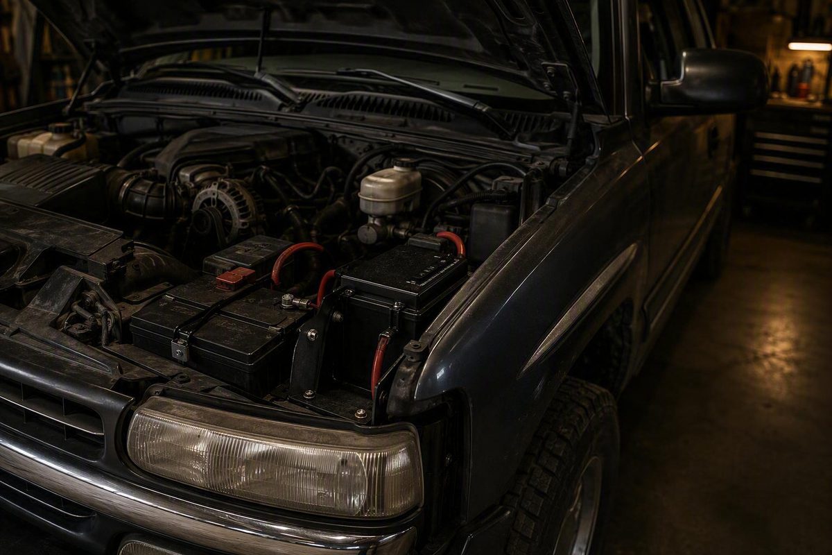
Adding an isolated auxiliary battery to a gasoline-powered 2000 Chevrolet Silverado is possible, but the available evidence does not support a universal bolt-in procedure. The strongest vehicle-specific example is a third-party installation published in 2001 and performed on a 2000 Silverado 1500 Z71 with a 5.3-liter engine and a 130-amp alternator. It placed a second battery at the rear of the passenger-side engine bay and connected it through a continuous-duty isolation relay so accessory use would not intentionally discharge the starting battery.
That historical installation establishes a workable layout, not a current Chevrolet-approved design. Tray fit, brace treatment, cable size, circuit protection, battery chemistry, charging control, grounding, torque values, and connection points must be verified for the exact truck and selected components.
This article is therefore a pre-installation planning guide rather than a complete wiring specification. Before energizing the system, obtain applicable vehicle service information and current instructions for the battery, tray, isolator or charger, cable terminals, and protection devices. High-current design questions that remain unresolved should be reviewed by a qualified automotive electrician.
What the documented 2000 Silverado installation does—and does not prove
The period installation involved a gasoline-powered 2000 Silverado 1500 Z71 with a 5.3-liter engine and 130-amp alternator. It used a dedicated passenger-side tray, a 200-amp continuous-duty isolation relay, labeled pre-cut 2-gauge copper cables, an optional battery-manager switch and harness, and an Optima battery. The battery sat near the firewall, and the radiator overflow tank was temporarily moved while the tray was installed, according to the documented 2000 Silverado installation.
The article listed these period components:
- Auxiliary tray kit: 34-959-5
- Relay and cable kit: 34-959-5R
- Battery-manager switch and harness: 34-959BM-5
- Battery: 18-800U, described as an Optima 800U
These are historical references only. The evidence does not establish their present availability, unchanged specifications, compatibility with current batteries, or fitment on a particular truck. A modern system should be based on measured space and verified electrical requirements rather than the assumption that a decades-old kit remains suitable.
Later Silverado and other GMT-800 installations provide useful context. They also show batteries in the rear passenger-side area, factory-style trays, and different isolator arrangements. They do not verify identical mounting holes, braces, factory connectors, cable routes, charging points, or grounds on every 2000 Silverado.
This guide is limited to gasoline-powered configurations. The evidence does not establish a procedure for diesel trucks, which may have different battery arrangements, starting-current requirements, charging systems, and underhood packaging.
Before selecting parts, record:
- Engine and fuel type
- Cab, trim, and option package
- Alternator model and rated output
- Emissions equipment and other underhood options
- Existing passenger-side engine-bay layout
- Coolant-reservoir position and available movement
- Air-cleaner and intake-duct clearance
- Existing fender, hood, and body braces
- Candidate tray dimensions and mounting method
- Battery length, width, height, terminal style, and terminal position
- Hood clearance above the case and terminals
- Access for installing and removing the battery
- Intended accessories and their manufacturer-rated continuous and surge loads
- Expected engine-off operating time
- Starting- and auxiliary-battery chemistry
- Auxiliary-battery charging requirements
- Proposed cable route and complete circuit length
- Candidate charging and grounding points
Do not treat “2000 Silverado” as a complete fitment specification.
No supplied source provides a Chevrolet-approved auxiliary-battery procedure for every 2000 Silverado. The evidence also lacks a current complete parts list, universal wiring diagram, validated protection schedule, structural guidance, and torque specifications. Resolve those items through current component instructions, applicable vehicle service information, and qualified review before installation.
A practical planning worksheet can help expose missing information:
| Design item | Information to record | Where to verify it |
|---|---|---|
| Accessory load | Manufacturer-rated continuous and surge demand for each accessory | Accessory instructions or data label |
| Engine-off use | Which loads will operate together and for how long | Intended operating plan |
| Battery | Dimensions, terminal layout, chemistry, capacity, and charge requirements | Battery manufacturer |
| Charging control | Continuous rating, control logic, environmental limits, and compatibility | Isolator or charger manufacturer |
| Cable route | Actual path length, return path, heat exposure, bundling, and bends | Measured on the truck |
| Cable selection | Required conductor size for the calculated current, route, and voltage-drop limit | Current cable and device instructions |
| Protection | Device type, rating, interrupt capacity, and permitted distance from each source | Protection-device and cable instructions |
| Alternator demand | Vehicle demand, simultaneous accessories, and intended recharge demand | Vehicle data and measured system assessment |
| Mounting | Tray fit, hold-down, brace treatment, hood clearance, and service access | Dry fit and applicable vehicle information |
If any row remains unresolved, the system is not ready to be energized.
Choose the electrical design before buying parts
The first design decision is whether the batteries will be permanently paralleled or isolated. These arrangements serve different goals.
In a permanently parallel system, positive is connected to positive and negative to negative. The batteries operate as a shared bank. This increases combined storage, but accessories connected to the bank can reduce the available charge in both batteries. Permanent parallel wiring therefore does not, by itself, preserve an independent starting reserve.
Some owner instructions for 1999-and-newer Silverados describe direct parallel wiring and locate the tray between the coolant reservoir and firewall. Their mechanical observations can help identify the general area, but the electrical arrangement does not meet the goal of reserving the starting battery and does not provide a complete protection design. That distinction is visible in the owner-posted parallel-battery instructions.
An isolated system connects the batteries for charging under selected conditions and separates the positive charging path when the engine is off. Accessories are assigned to the auxiliary side, leaving the starting battery for starting and normal vehicle systems. This is the principal design considered here.
Three charging-control categories are relevant:
RUN-triggered continuous-duty solenoid. A high-current relay closes when its low-current coil receives the intended control signal. When control power is removed, the relay opens. The relay, trigger circuit, and control wiring must be selected and installed according to their current instructions.
Voltage-sensing isolator. This device combines and separates the batteries according to its own sensing logic. It may avoid the need for a dashboard switch or ignition-trigger wire, but its thresholds, continuous-current rating, and compatibility still require verification. Owner discussions describe both basic ignition-controlled solenoids and automatic voltage-sensing devices, but they are not model-specific engineering instructions for a 2000 truck. See the comparison of parallel and isolated arrangements.
DC-to-DC charger. The supplied Silverado examples do not document a DC-to-DC installation, so its selection and configuration must come from the battery and charger manufacturers or a qualified designer.
A charging relay must be selected for continuous operation at the design current. Use the selected device’s instructions to establish ratings, wiring, environmental protection, and control requirements.
Isolation also does not automatically provide self-jump capability. If self-jumping is a design objective, the cables, lugs, terminals, switching device, protection, control logic, and return path must be evaluated specifically for that operating mode.
For readers whose priority is preserving starting power, an isolated arrangement is the appropriate planning path. Permanent parallel wiring remains possible for other applications, but it accepts the risk that accessory use can draw down the shared bank.
Build a parts list from specifications, not obsolete kit numbers
A specification-based shopping list should include:
- A vehicle-compatible auxiliary-battery tray
- A positive mechanical battery hold-down
- A battery that fits the tray and available space
- A continuous-duty isolator, relay, or charging device compatible with the system
- High-current cable selected for the completed design
- Cable lugs matched to the conductor and connection studs
- A crimping method approved for the selected cable and lugs
- Adhesive-lined heat-shrink tubing where specified
- Insulating covers for positive terminals and exposed positive studs
- Abrasion-resistant loom or other suitable cable protection
- Grommets or approved pass-through fittings where required
- Strain relief at batteries, isolator studs, protection devices, and distribution points
- Insulated cable supports
- Low-current control wire
- A properly protected control-power source
- High-current overcurrent-protection devices selected for the design
- An auxiliary fuse or distribution panel
- Suitable tray, isolator, protection-device, and cable-support hardware
- Terminal and mounting-point corrosion protection
- Durable circuit and cable labels
One GMT-800 owner addressed this with protection at both battery ends, but the reported 150-amp devices, 2-AWG cable, and 200-amp isolator are only one owner’s choices, not universal ratings. The final protection arrangement must be established from the selected cable, device instructions, fault-current conditions, expected load, and installation geometry. The example is documented in a GMT-800 isolated-battery write-up.
Accessory circuits should be planned through a protected auxiliary distribution point.
Cable size cannot be copied from battery count or another truck. Provide the cable or system designer with:
- Complete positive and return-path length
- Expected continuous charging current
- Accessory continuous and surge demand
- Desired voltage-drop limit
- Underhood and route temperature
- Cable insulation rating
- Bundling or enclosure conditions
- Proximity to heat sources
- Lug, stud, and terminal ratings
- Protection-device characteristics
- Charging-device capacity
- Any intended starter-current mode
The historical values show the range of individual projects, not a specification. The 2000 period installation used 2-gauge cable and a 200-amp continuous-duty relay. A later high-load 2003 Silverado build used 1-gauge battery cable and a 250-amp control system while also upgrading other charging-system components. These numbers should remain tied to those particular installations.
Work equipment should be selected for the components and procedure, including:
- Appropriate eye protection
- Suitable hand tools
- A digital multimeter configured for the intended measurement
- A cable-lug crimper approved for the lug and conductor
- Cable cutters sized for the conductor
- Heat-shrink equipment
- Loom, grommets, clamps, ties, and fastening supplies
- Tools appropriate for the selected tray
- A way to mock up the cable route before cutting
- Current component instructions and applicable vehicle information
Do not adopt the makeshift termination methods found in some owner builds. Use the cable and terminal manufacturers’ approved preparation, crimping, sealing, and inspection process. Positive terminals and studs should receive the covers specified for the installation, and cable routing should be completed only after the required protection and support method has been designed.
Verify and mount the passenger-side battery tray
The recurring reported location is the rear of the passenger-side engine compartment, near the firewall and coolant-reservoir area.
In the documented 2000 installation, the installer removed the passenger-side upper and lower fender supports, temporarily moved the radiator overflow tank, and fitted a replacement tray where the lower support had been. The period tray reportedly used four existing 13 mm nuts and one 10 mm bolt. Those measurements identify wrench sizes in that historical installation; they are not torque specifications or proof that a current tray mounts the same way.
A documented 2003 Silverado project also used the rear passenger-side area. Its factory-style tray replaced a brace, required a minor bend, and attached with existing hardware. That build provides useful context but cannot establish structural acceptability or fitment on a 2000 truck. Its tray, battery, cable, and isolator installation can be reviewed in the 2003 Silverado dual-battery project.
Dry-fit the mechanical system before ordering finished cables or beginning electrical work:
- Inspect the tray area for corrosion, collision damage, prior repairs, aftermarket wiring, and nonstandard equipment.
- Compare the tray with existing mounting points without drilling, cutting, or bending anything.
- Determine whether the coolant reservoir must move and whether the selected tray instructions address that movement.
- Position the unloaded tray and inspect its contact with the intended mounting surfaces.
- Place the disconnected battery in the tray.
- Fit the specified hold-down and confirm that it captures the battery mechanically.
- Check hood closure and clearance above the battery case and terminals.
- Check the coolant reservoir, air cleaner, intake ducting, hoses, wiring, and brackets.
- Consider whether permitted battery movement could bring a terminal near grounded metal.
- Confirm that the battery can be removed later without unsafe disassembly.
- Assess tray rigidity with the battery’s weight in mind.
- Plan cable exits that do not turn the cables into restraints or rub points.
This is an inspection checklist, not authorization to modify a brace. Owner reports describe removing braces, replacing a brace with a tray, bending a tray, or trimming a tab, but those reports do not establish that a particular structural change is harmless. Verify brace treatment through applicable vehicle information or a qualified body-repair professional.
There is no universal instruction here to trim a firewall tab or drill new holes. If the selected tray requires an unverified structural change, stop and resolve that issue before continuing.
The battery needs a hold-down designed for the tray and battery. The historical and later documented installations both secured the battery in a dedicated tray; neither supports relying on cables to restrain it. Verify the hold-down, hardware, tightening requirements, and permitted battery movement through current component instructions.
Map the high-current charging and grounding circuit
Draw the complete proposed circuit before measuring or cutting cable. The conceptual positive path for an isolated system is:
Verified charging source or starting-battery positive
    → protection arrangement specified for that energized source
    → high-current cable
    → isolator or charging-device input
    → isolator or charging-device output
    → protection arrangement for the auxiliary-energized section
    → auxiliary-battery positive
The accessory path is separate:
Auxiliary-battery positive
    → designed near-battery protection
    → auxiliary distribution or fuse panel
    → individually protected accessory circuits
This is a planning map, not a universal terminal diagram. The protection-device type, position, rating, and interrupt capacity must be established for the actual conductors, batteries, charging device, and fault conditions.
Reported GMT-800 installations have used different charging points, including the starting-battery terminal, starter post, factory junction block, and fuse-panel post. A 2003 Silverado owner, for example, reported an isolator-to-starter-post route, while another project retained a factory junction block. The differences are summarized in the Silverado second-battery discussion, but none of those arrangements is established as correct for every 2000 configuration.
Select a charging point only after checking the exact truck’s wiring information and inspecting the relevant conductor, stud, enclosure, terminal, and downstream connections. The installation must not assume that a convenient factory stud has capacity for an added circuit or that attaching there preserves the intended factory protection.
Grounding also varies among the examples. The historical 2000 installation used the engine block. A 2003 project used a frame location, and another GMT-800 owner used a chassis point behind the engine. These are installation reports, not universally approved ground locations.
The proposed return path should be evaluated under the expected load, including the condition of relevant engine, frame, and body bonding. Do not designate a dipstick-tube bolt, body mount, firewall stud, or other reported point as approved merely because it appeared in another build. Confirm that the fastener can accept the connection without compromising the component it already secures.
Plan the positive-cable route around:
- Exhaust and other heat sources
- Sharp sheet-metal edges
- Exposed fastener threads
- Steering and throttle components
- Belts, pulleys, and fans
- Hood hinges and pinch points
- Existing hoses and wiring
- Locations requiring abrasion protection
- Approved pass-throughs and grommets
- Cable-support and strain-relief points
- Access to isolator and protection-device terminals
- Positive-terminal and stud covers
The historical 2000 procedure specifically kept its main positive cable disconnected while routing it along the firewall and away from heat. Use that as a minimum planning lesson, then follow the more detailed routing, support, and protection requirements supplied with the current cable, tray, isolator, and protection devices.
Wire automatic isolation and the optional cab control
A RUN-triggered continuous-duty relay contains two distinct circuits. Its large contacts carry the charging path. Its low-current coil controls whether those contacts are open or closed.
When the verified control source energizes the coil, the relay closes and connects the charging source to the auxiliary side. When control power is removed, the relay opens the intended positive charging path. Relay current ratings, control voltage, environmental protection, terminal limits, and duty cycle must suit the design.
In the historical 2000 installation, the relay was mounted to the auxiliary tray and its coil-negative terminal was connected to a tray mounting bolt. That is a description of one installation, not proof that any tray bolt will provide a suitable ground on another truck. The selected relay’s ground path must be verified according to its current instructions.
The optional period battery-manager switch was mounted under the dashboard. Its harness passed through a grommeted firewall opening, connected to the relay, and received control power from a circuit that the installer was told to verify as energized in RUN but not in ACCESSORY or START. Those details appear in the same period installation account.
Do not copy an assumed fuse position, connector, or wire color from another vehicle. Identify the proposed control source from applicable wiring information and verify its behavior in all relevant key positions. The control circuit’s protection and permitted added load must be established from current instructions.
The historical firewall-hole location is not universal drilling guidance. Hidden factory wiring, insulation, HVAC equipment, brake components, and structural material can differ with configuration and previous repairs.
Safer planning options are to:
- Use an existing verified pass-through if it has suitable capacity and can be resealed without damaging the factory harness.
- Omit an optional dashboard control.
- Choose a compatible voltage-sensing isolator that does not require a cab trigger.
- Have a qualified professional inspect and execute any necessary firewall penetration.
A manual override changes the control logic; it does not prove that the high-current circuit can carry starter current. Treat self-jump operation as a separate design requirement.
Follow a de-energized, inspection-first installation sequence
Battery work presents ignition and high-current hazards. The period installation warns that batteries can be explosive and directs the installer to wear eye protection and remove jewelry. Work away from flames and sparks, prevent tools from bridging terminals, and follow the safety instructions supplied by the battery and vehicle manufacturers.
Before disconnecting power, photograph and label the existing battery wiring. Check applicable service information for power-removal consequences and record any settings that may be lost. Aftermarket alarms, audio equipment, and other accessories may introduce additional requirements.
Because the available sources do not provide a validated universal procedure, use the following only as a project-control sequence. Component-specific steps, connection order, tightening values, and final energization instructions must come from current manufacturer and vehicle information.
-
Inspect the truck. Confirm the engine, alternator, passenger-side layout, existing grounds, aftermarket wiring, and proposed cable route.
-
Finish the design. Resolve the load profile, charging architecture, cable selection, protection arrangement, grounding path, and alternator assessment.
-
Disconnect the starting side as directed. Follow applicable vehicle and installed-equipment instructions before high-current conductors are routed or terminated.
-
Keep the auxiliary battery electrically isolated. Do not introduce an energized loose battery while tray, cable, or protection-device work remains incomplete.
-
Complete the mechanical work first. Install only a verified tray and hold-down arrangement, then dry-fit the disconnected battery.
-
Recheck clearance. Inspect hood closure, terminals, reservoir position, intake components, hoses, wiring, hold-down engagement, and service access.
-
Mount the charging and protection devices. Use the mounting surfaces, orientation, hardware, clearances, and terminal covers specified for those components.
-
Measure the actual cable route. Include bends, service access, terminal orientation, support positions, and protection-device locations.
-
Have the cables fabricated correctly. Use compatible conductors, lugs, preparation methods, crimp tooling, sealing, and inspection criteria.
-
Route conductors while de-energized. Apply the component makers’ requirements for heat clearance, abrasion protection, grommets, supports, and strain relief.
-
Install the designed protection. Confirm the arrangement against the cable and protection-device instructions rather than copying another build’s ratings.
-
Install the ground and required bonding. Prepare and tighten connections to the applicable specifications and verify the intended return path.
-
Route the control circuit. Protect it according to the device instructions and avoid any uninspected firewall penetration.
-
Trace the installation point by point. Compare every conductor and connection with the final circuit drawing.
Before final connection, confirm:
- Polarity at every destination
- Correct charging-device input and output routing
- Cable lugs formed and inspected as specified
- Positive terminals and studs covered
- Designed protection devices installed
- Cable covering present where the route requires it
- Pass-throughs properly protected and sealed
- Cable supports and strain relief complete
- No contact with heat, moving parts, or pinch points
- Ground and bonding paths resolved
- Battery positively restrained
- Hood and surrounding-component clearance
- No loose hardware or tools in the engine bay
Make final connections only under the applicable vehicle and component instructions. The evidence does not establish a universal connection order or torque value.
Arrange professional inspection before energizing if the project includes firewall drilling, uncertain brace treatment, questionable grounding, custom high-current cable fabrication, unexplained factory wiring, or unresolved cable and protection calculations. A later Silverado build demonstrates that tray installation, cable fabrication, grounding, isolator control, and final testing form one integrated project—not independent shortcuts that can be selected without a complete design.
Commission the system before connecting demanding accessories
The historical 2000 article ends before providing a complete final-connection and testing procedure. It should not be treated as a finished Chevrolet-approved commissioning process.
Commissioning should follow the current instructions for the battery, charging device, relay, protection devices, and test equipment. If those instructions do not provide a complete and mutually compatible process, have an automotive electrical specialist conduct or validate the test.
Begin with inverters, amplifiers, auxiliary lighting, and other demanding accessories disconnected. Do not improvise high-current measurements. Any instrument must be rated, connected, and configured for the measurement being made; use professional assistance if the required test method is uncertain.
For this system, “isolated” means that the intended positive charging path between the starting and auxiliary batteries is open when commanded.
With the engine off and the isolator commanded open, the commissioning plan should verify:
- Correct polarity at both batteries and the auxiliary distribution point
- The intended positive charging path is open
- The control circuit has the intended key-position behavior
- The relay does not remain energized when it should be open
- A design-approved auxiliary load is supplied from the auxiliary side
- No unintended positive parallel path defeats isolation
After those checks pass, start the engine without immediately applying a large accessory load. Verify that the charging device follows its intended control logic and that observed charging behavior is appropriate for the selected battery chemistry and device configuration.
Do not use one universal voltage as the pass-or-fail threshold. The supplied examples report particular readings on particular trucks, but they do not establish a standard for another installation. Compare measurements at the selected charging source, charging-device input, output, auxiliary-battery terminals, and relevant return points using the procedure specified for the completed design.
If readings differ unexpectedly, do not respond by increasing a fuse rating or changing cable by guesswork. A qualified test procedure may include loaded voltage-drop measurements across:
- Charging source to charging-device input
- The closed charging device
- Charging-device output to auxiliary-battery positive
- Connections across protection devices and junctions
- The auxiliary-battery return path
- Relevant engine, frame, and body bonding paths
The test load must remain within the completed design and the test equipment’s instructions. The supplied owner projects do not establish a universal current level or test duration.
During commissioning, stop and investigate if the system shows:
- Reversed polarity
- Unexpected battery discharge
- Relay chatter
- Failure to connect or disconnect
- Dimming or unstable operation
- Abnormal heating at terminals, lugs, cables, or protection devices
- Electrical or battery odor
- Arcing or discoloration
- Loose or moving cables
- Hood interference
- Reservoir, intake, hose, or wiring contact
Do not bypass an opened protection device, bridge isolator studs, or substitute a larger rating simply to continue testing. The GMT-800 owner example with fuses at both battery ends illustrates one designed arrangement; it does not validate bypassing protection or changing ratings without recalculating the system.
After the initial operating check, shut the system down according to the component instructions. Reinspect cable supports, battery restraint, loom position, terminal security, corrosion protection, abrasion points, and evidence of abnormal heat.
| Symptom | Stop and inspect |
|---|---|
| No auxiliary charging | Relay control, charging-device operation, protection devices, polarity, cable continuity, selected charging point, and return path |
| Batteries remain positively connected with the engine off | Trigger circuit, relay contacts, manual-switch position, voltage-sensing logic, and unintended parallel paths |
| Isolator chatters | Control voltage, coil ground, loose connections, battery condition, charging stability, and device compatibility |
| Unexpected voltage difference | Cable route, cable selection, crimps, studs, protection-device connections, isolator contacts, grounds, and bonding |
| Fuse or breaker opens | Short circuits, pinched conductors, excessive current, accessory demand, cable selection, and protection-device selection |
| Cable, lug, or protection device heats abnormally | Excessive current, poor termination, corrosion, damaged conductor, insufficient contact area, or an unsuitable component |
Alternator adequacy cannot be determined from the number of batteries. A second battery adds storage, while recharging it adds demand to the charging system.
The documented high-load 2003 Silverado combined its dual-battery installation with an upgraded alternator because that truck had substantial added electrical equipment. That example does not establish that every auxiliary-battery system requires an alternator upgrade, nor does the 130-amp alternator reported on one 2000 truck prove adequacy for an unspecified load.
Frequently asked questions
Where is the auxiliary battery mounted on a 2000 Chevy Silverado?
The documented location is at the rear of the passenger-side engine compartment near the firewall, in the area between the coolant reservoir and firewall. A dedicated tray occupies space associated with existing passenger-side supports.
Confirm fitment by dry-fitting the exact tray, battery, and hold-down. Check hood and terminal clearance, reservoir position, air-cleaner clearance, hoses, wiring, braces, and battery-removal access. Do not remove or trim a brace solely because an owner report describes doing so.
Do I need an isolator for a Silverado dual-battery system?
Use an isolated architecture if the objective is to operate accessories from the auxiliary battery while preserving an independent starting reserve. Permanently paralleled batteries behave as a shared bank, allowing accessory use to reduce the charge in both.
Possible designs include a RUN-triggered continuous-duty relay, a compatible voltage-sensing isolator, or a professionally evaluated DC-to-DC charger. The correct choice depends on the charging system, battery requirements, expected current, and desired control behavior.
Will the stock 130-amp alternator charge both batteries?
The documented 2000 Silverado had a 130-amp alternator, but that number does not establish adequacy for another truck or accessory package.
Create a load budget from the manufacturer-rated demand of every load expected to operate simultaneously. Then evaluate the remaining charging capacity and desired auxiliary-battery recharge demand under the truck’s relevant operating conditions.
What cable size and fuse rating should I use?
There is no universal cable or protection rating for a 2000 Silverado auxiliary-battery installation.
Individual projects have reported 1-gauge or 2-gauge cable, 200- to 250-amp switching devices, and—in one GMT-800 owner installation—150-amp protection at both battery ends. Those are historical examples, not specifications for another truck.
Can the auxiliary-battery isolator be used to jump-start the truck?
Not unless the complete system has been designed and validated for starter current. Normal charging capability does not prove that the isolator, cables, lugs, terminals, protection devices, grounds, and controls can safely support cranking.
A switch labeled “combine” or “override” establishes only a control function. If emergency starting is an objective, treat it as a separate operating mode requiring its own engineering review.
Final decision gate before energizing the system
Proceed only after all of the following are true:
- The passenger-side tray fits without unresolved interference.
- Brace treatment has been verified as acceptable.
- The battery has a suitable mechanical hold-down.
- Hood and terminal clearance have been confirmed.
- The complete positive and return routes have been measured.
- Continuous and surge loads have been documented.
- Cable selection has been completed from current technical instructions.
- Protection type, rating, placement, and interrupt capacity have been resolved.
- The charging device is suitable for continuous operation and the selected control strategy.
- Battery chemistry and charging requirements are compatible with the design.
- Charging and grounding points have been verified for the exact truck.
- Firewall routing requires no uninspected or unapproved penetration.
- Final connection and tightening instructions are available for every component.
- Engine-off isolation and engine-running charging can be commissioned under a validated test plan.
- The installation has been inspected for abnormal heating, abrasion, movement, and interference.
The historical 5.3-liter 2000 Silverado installation demonstrates that an auxiliary battery can occupy the rear passenger-side engine-bay location. It does not resolve fitment, structural, firewall, grounding, protection, or high-current design questions for every truck. Refer any unresolved item to applicable vehicle service information, current component manufacturers, or a qualified automotive electrician before energizing the system.