
12 min read ·
Choose the Right Way to Disconnect—or Maintain—Your Car Battery
Choose a charger lead for maintenance charging or a rated switch for isolation, with checks for cranking capacity, post fit, clearance and alternator paths.
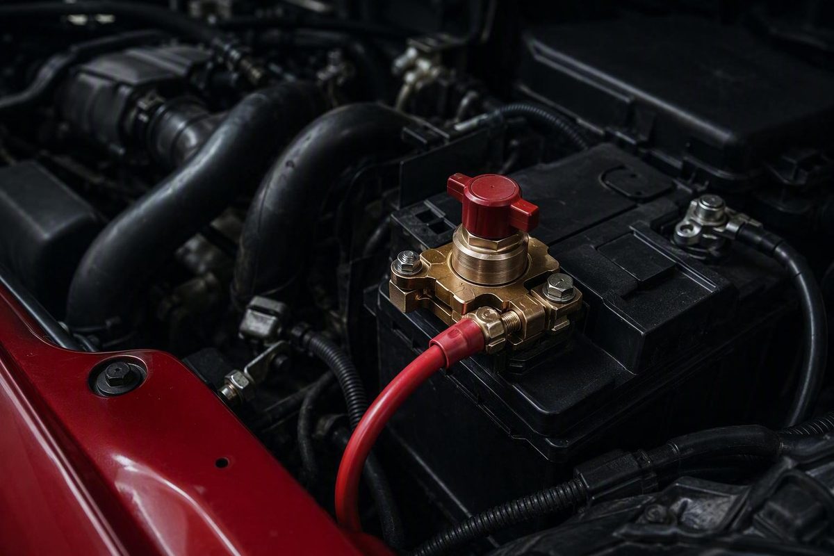
A battery quick disconnect can refer to two very different products. Choose a main-circuit battery switch when you need to isolate the vehicle’s electrical system for storage or service. Choose a fused charger lead when you want a convenient connection for a compatible battery maintainer. Never use a typical charger connector for starter current or whole-vehicle isolation unless the documentation for that exact product explicitly permits it.
This guide covers low-voltage starting and accessory batteries. It does not apply to an EV’s high-voltage traction-battery service disconnect.
First decide what you mean by “quick disconnect”
A manual battery disconnect is an operator-actuated switch installed in the main battery circuit. Opening it separates the battery from some or all of the vehicle’s electrical system. Common reasons include storage, maintenance and intentional electrical isolation.
A charger quick connector serves a different purpose. Battery Tender groups ring-terminal harnesses, SAE extension cables and adapters as charging and maintenance accessories. A ring-terminal harness remains attached to the battery so a compatible charger can be connected without repeatedly removing the battery cables.
Use this two-path decision:
- Need to disconnect the vehicle from the battery? Choose a properly rated main-circuit disconnect switch.
- Need convenient access for maintenance charging? Choose the charger manufacturer’s compatible ring-terminal lead, extension or adapter.
A charging connector may look substantial, but its wire, terminals and fuse may be intended only for charger-level current. Do not place it in the starter circuit or treat it as a removable main battery cable without an explicit rating for that service.
A disconnect switch is also not automatically a fuse, circuit breaker or other overcurrent-protection device. It opens the circuit when operated, but it does not necessarily respond automatically to excessive current. Any required circuit protection remains a separate design consideration.
Quick-disconnect types compared
Choose by required function, not by whether a product listing happens to include the words “battery quick disconnect.”
| Type | Connection and function | Principal use and starter-current potential | Critical checks |
|---|---|---|---|
| Negative-post knob switch | Fits between a compatible top-post battery’s negative terminal and cable | Routine storage or service isolation; suitable for starting loads only when adequately rated | Post size, polarity, cranking rating, cable angle, clearance and connection security |
| Heavy-duty rotary, keyed or lever switch | Installed in a main battery cable, commonly near the battery or on a panel | Fleet, RV, marine, equipment or service isolation; some models support starting loads | Voltage, continuous and cranking ratings, interruption limits, pole count, sealing and mounting |
| Remote solenoid disconnect | Opens the main circuit through an electrically controlled relay or solenoid | Remote or automated isolation; high-current versions are available | Main and control voltage, continuous and inrush ratings, standby draw, fail-state and sealing |
| Multi-pole or alternator-aware switch | Interrupts more than one path, potentially including alternator or ignition circuits | Engine-shutdown or engineered isolation systems rather than simple storage disconnection | Wiring diagram, pole sequence, alternator arrangement and applicable equipment or competition rules |
| Fused ring-terminal charging lead | Connects a compatible charger or low-current accessory directly to the battery | Maintenance charging, not whole-vehicle isolation or starter current unless expressly rated | Charger compatibility, voltage, fuse, polarity, wire capacity, routing and connector condition |
A negative-post knob switch is the simplest terminal-mounted format. On common examples, hand-tightening the knob completes the circuit and loosening it disconnects power. A removable knob may discourage casual unauthorized use, but it is not a proven vehicle-security system.
Heavier manual switches use rotary knobs, removable keys, levers, push buttons or T-handles. Their larger construction does not by itself establish starter compatibility; the exact electrical ratings and permitted operating conditions still control.
Remote disconnects use a solenoid or magnetic mechanism so the battery can be isolated through a cab switch, timer or battery-management system. Littelfuse, for example, lists remote products with continuous-current ratings from 150 to 500 amps, along with different pole and sealing options, demonstrating why remote disconnect selection must be part-specific.
Multi-pole and alternator-aware switches serve another purpose. They can form part of a system intended to interrupt multiple conductors or stop a running engine. A basic two-terminal battery switch does not automatically provide that function.
It does not replace a master battery cutoff.
How to size a battery disconnect without guessing
Start with the vehicle’s electrical system and the available installation space. A switch that physically fits the battery post but cannot handle the required current is not compatible.
Check all of the following before ordering:
- System voltage: Match the documented DC-voltage range to the battery system.
- Continuous current: Confirm how much current the switch can carry continuously under its stated conditions.
- Cranking or inrush current: Look for a separate short-duration rating and the permitted duration.
- Test conditions: Check for temperature, duty-cycle or other conditions attached to the ratings.
-
Battery-post dimensions: Verify the actual terminal style and diameter instead of relying on a “universal” description.
-
Cable geometry: Check cable length, approach angle, strain and whether the switch’s added height or offset will distort the connection.
- Compartment clearance: Confirm clearance from the hood, battery cover, body panels and nearby conductive parts.
- Number of poles: Determine whether one circuit or several paths must be interrupted.
- Alternator arrangement: Establish whether opening the main battery cable achieves the intended isolation.
- Environment: Account for water, dust, road salt, vibration, engine-compartment heat and cleaning exposure.
- Installation requirements: Obtain the wiring diagram, terminal-torque specification, mounting instructions and permitted operating conditions for the exact model.
- Application-specific approvals: Where marine, competition, fleet or equipment rules apply, verify the required approvals. A certification label alone does not establish vehicle fit or starter suitability.
Continuous and cranking current are different ratings. A switch may carry a moderate current indefinitely yet be unsuitable for the starter motor’s brief demand. Conversely, a large “instantaneous” figure without a stated duration and test method does not establish starter compatibility.
The available product range illustrates the need for exact-model checking. Littelfuse lists manual switches for 12-, 24- and 48-volt DC systems with continuous ratings from 40 to 600 amps. Its catalog also includes single- and double-pole designs with differing ingress-protection levels. Those are portfolio ranges, not characteristics shared by every model; consult the specific switch and datasheet.
Do not judge suitability from price, appearance, a marketplace title or a category filter. Verify the exact model’s rating definitions, terminal arrangement, operating temperature, mounting limits, torque instructions and any approvals required for the application. If usable cranking or inrush data is unavailable, ask the manufacturer or choose a product with adequate published documentation.
When a disconnect helps—and when it only hides the problem
Opening a correctly installed switch stops vehicle-side parked loads from drawing power through the interrupted path. That can be useful when a vehicle is intentionally stored with its electrical system shut down.
It does not diagnose or repair abnormal battery discharge. Possible causes include:
- A glovebox, trunk, dome or exterior light left on
- An improperly wired stereo, dash camera, alarm or other accessory
- A relay that remains energized
- A short or damaged circuit
- Faulty alternator diodes
- A weak or aging battery that mimics a drain problem
These are among the possible causes identified in an overview of recurring parked-battery discharge. Acceptable key-off draw varies by vehicle, installed equipment, module sleep state and battery condition, so there is no useful universal threshold for every car.
Choose among three responses:
- Diagnose and repair the fault when a frequently driven vehicle repeatedly loses charge.
- Use a compatible maintainer when the vehicle is stored near charging power and preserving battery charge is the main objective.
- Install a properly rated disconnect when intentional vehicle-side isolation is appropriate and the consequences of losing power are acceptable.
A fused memory bypass changes the result. It can keep selected circuits powered while the main switch is open, potentially preserving a clock or radio memory. Because current still has a path, the vehicle is not fully isolated, and a load on the bypassed circuit can continue discharging the battery.
Cautious installation outline for a negative-post knob switch
This is a general outline only for a compatible negative-post, top-post switch. The vehicle manual and the instructions for the exact switch take priority.
- Prepare the vehicle. Park securely, switch off the ignition and accessories, disconnect charging equipment and keep ignition sources away from the battery area. Check the vehicle manual for any prescribed shutdown procedure.
- Identify the consequences of power loss. Determine whether the vehicle documentation calls for security codes, battery registration, initialization or relearn work after reconnection.
- Remove the negative cable first. Prevent the disconnected cable from springing back onto the battery post.
- Fit the switch to the negative post. Confirm that it is designed for that post size and polarity. Secure it only as directed by the manufacturer.
- Attach the vehicle’s negative cable. Connect it to the switch output in the documented orientation without twisting or stretching the cable.
- Inspect the installation. Check post engagement, polarity, insulation, cable strain, hood or cover clearance and connection security before restoring power.
- Operate the switch as documented. Some knob switches connect when hand-tightened and disconnect when loosened; other products use a quarter-turn lever, key or separate control.
- Verify normal operation. Restore power and confirm that the vehicle starts and that its electrical systems behave normally.
General installation material for terminal-mounted switches supports turning off the ignition, disconnecting accessories, removing the negative cable first and checking connections for looseness or corrosion. It also stresses that post fit and current capacity must match the application; treat the exact product instructions as controlling.
After installation, stop using the disconnect if you notice slow cranking, intermittent electrical operation, a loose terminal, corrosion, unusual heat or odor, discoloration or damaged insulation. These symptoms can have several causes, including a poor connection, incorrect fit or an inadequate component, and they require inspection rather than guesswork.
Obtain qualified help if the ratings, terminal fit, wiring arrangement or vehicle procedure are uncertain. Do not substitute generic cable sizes, fuse values or torque figures for the product and vehicle specifications.
Modern-vehicle and running-engine cautions
Disconnecting power may erase clocks, radio presets, ECU memory and learned settings or affect alarms and other vehicle-specific functions. Some vehicles may require battery registration, security-code entry or an initialization or relearn procedure. These requirements cannot be determined reliably from vehicle age or brand alone; check the applicable owner or service information.
Do not open a basic battery disconnect while the engine is cranking or running unless the switch and the complete electrical system are expressly engineered for loaded interruption.
Opening only the battery path may also fail to stop a running engine because the alternator can continue powering the ignition and other electrical loads. General disconnect guidance warns against operating a basic switch during cranking or while the engine is running and explains that a full shutdown may require alternator-output or ignition-circuit switching; see the JEGS battery-disconnect wiring guide.
Emergency and competition systems may therefore need multiple poles, a dedicated alternator arrangement or a secondary ignition cutoff. The complete installation must satisfy the applicable rules. A simple battery-post knob is not a substitute for an engineered race or emergency cutoff.
If a fused memory bypass is fitted, remember that the selected circuits remain energized even when the main switch is open.
Special cases: boats, remote systems, and multiple batteries
Marine and exposed installations require part-specific evaluation of sealing, corrosion resistance, conductor requirements and vibration capability. The switch should remain accessible while limiting exposure, and positive-lead overcurrent protection must follow the requirements of the specific system. General marine guidance calls for suitable conductors and terminals, an accessible dry mounting location and appropriate positive-lead protection, but the applicable manufacturer and marine requirements remain controlling.
Ingress-protection ratings can vary substantially within one catalog. Do not describe an entire switch range as waterproof because one model carries a high IP rating.
A remote solenoid disconnect can suit a fleet vehicle, equipment installation or battery compartment that is difficult to reach. It may permit control through a cab switch, timer or battery-management system. Confirm:
- System and control voltage
- Continuous-current rating
- Inrush or cranking rating and duration
- Single- or double-pole arrangement
- Environmental sealing
- Standby current
- Control wiring and intended fail-state
Remote operation adds convenience and automation, but it also adds control wiring and components that must be included in troubleshooting.
Dual- and multi-battery systems may require one disconnect per battery, a purpose-built selector or an engineered multi-pole arrangement. Before treating the system as isolated, map every alternate power path, including auxiliary batteries, alternators, converters, solar controllers, chargers and memory-bypass circuits. Retailer guidance for marine and dual-battery installations similarly emphasizes alternate arrangements and purpose-built switching; consult the applicable system guidance before wiring.
Series, parallel, marine, race and other complex systems warrant professional design review. The objective is not merely to insert a switch but to isolate every intended circuit without creating an undersized conductor, an unprotected positive lead or an unexpected energized path.
Compact buying checklist: Define the function first, then verify system voltage, continuous current, documented cranking capacity and duration, post fit, cable clearance, pole count, alternator paths and environmental protection. Use a charger lead only for compatible charging, a properly rated switch for intentional isolation, and diagnosis rather than a cutoff when a frequently used vehicle repeatedly loses charge.
Should a battery quick disconnect go on the positive or negative terminal?
For a basic terminal-mounted switch on a negative-ground passenger vehicle, the negative post is the common arrangement, and many knob switches are shaped specifically for that terminal. Positive-side, multi-pole and alternator-aware installations also exist. Use the location specified by the switch instructions and the vehicle or system design; never move a polarity-specific terminal switch to the opposite post simply because it appears to fit.
Can I use a Battery Tender quick-disconnect lead as a battery cutoff?
A typical Battery Tender-style ring-terminal lead should not be used as a battery cutoff. It is a fused charging connection rather than a switch in the main starter cable, so it neither isolates the whole vehicle nor carries starter current. The only exception would be an unusual product whose exact documentation expressly rates it for that service.
Why does the engine keep running after the battery is disconnected?
The alternator may still be supplying the ignition and other electrical loads. Opening only the battery connection does not necessarily interrupt the alternator-output or ignition path. Shut the engine off normally rather than experimenting with a basic disconnect while it is running. An emergency shutdown system must be designed to interrupt every required power path.
Is a 125-amp battery disconnect enough for my car?
The number alone is not enough. Determine whether 125 amps is a continuous, cranking or interrupting rating, then compare it with the vehicle’s documented demands.
For example, one seller states 125 amps continuous and 500 amps instantaneous for a disconnect but does not provide a duration for the higher figure in the published product details. Without a defined duration and test condition, the instantaneous rating does not establish starter compatibility. Verify the exact datasheet, vehicle requirements, terminal fit and cable arrangement before buying.